Zero-Downtime Playbook: Preventive Maintenance Tips for Tube Manufacturing Machinery

Unplanned downtime can halt your entire operation, costing you thousands, if not millions, in lost revenue and production delays. Imagine the stress of missed deadlines and spiraling repair costs, all because of a preventable failure. At XZS, we provide a proactive playbook for preventive maintenance, ensuring maximum uptime.
A zero-downtime playbook involves a strategic, proactive approach to equipment care, moving beyond simple reactive repairs. It integrates routine checks, cleaning, lubrication, and calibration into a holistic schedule. This strategy aims to eliminate unplanned stops, extend machinery lifespan, and guarantee consistent, high-quality output in tube manufacturing.
This isn't just about fixing things before they break; it’s about creating a culture of precision and reliability on your factory floor. In my 15+ years in this industry, I’ve seen firsthand how a well-executed maintenance strategy transforms a good operation into a great one. It’s the secret behind meeting tight tolerances and achieving superior material utilization, day in and day out.
Implementing a robust preventive maintenance (PM) program is the single most effective action you can take to protect your investment and boost your bottom line. Industry data shows that unplanned downtime costs the manufacturing sector an average of $260,000 per hour. Conversely, a well-implemented PM program can deliver a return on investment of up to 10x by reducing these failures by 70-75%. It shifts your focus from costly, chaotic repairs to controlled, scheduled upkeep. This playbook will guide you through creating a system that not only prevents failures but actively enhances the performance and longevity of your tube manufacturing machinery, turning a major operational liability into a competitive advantage.
How often should routine maintenance checks be conducted for tube manufacturing machinery?
Are you constantly fighting fires, with maintenance feeling more reactive than strategic? This approach leads to unpredictable schedules and spiraling costs. I advocate for a structured maintenance frequency, shifting from a chaotic "if it ain't broke" mindset to a predictable, performance-enhancing schedule that protects your bottom line.
Routine maintenance checks should be conducted on a tiered schedule: daily for high-wear components and visual inspections, weekly for detailed checks and lubrication, and monthly or quarterly for in-depth diagnostics and calibration, adjusted based on operational intensity, material types, and manufacturer recommendations.
Moving from a vague maintenance schedule to a data-driven one can feel like a monumental task, but it's the foundation of a zero-downtime operation. I remember working with a client, an automotive parts producer, who struggled with this very issue. Their maintenance was sporadic, largely driven by whatever operator was on shift. This resulted in inconsistent tube quality and, worse, a catastrophic bearing failure on their main forming stand that shut them down for three days, costing them a major order. By helping them implement a simple, tiered schedule—daily operator checks, weekly technician inspections, and monthly deep dives—we not only stabilized their production but also empowered their team. They began to own the health of their machinery. This transition is about more than just checklists; it's a cultural shift towards proactive control. It requires buy-in from the entire team, from the operator who notices a new vibration to the maintenance manager who analyzes long-term wear patterns. This systematic approach transforms your maintenance from a cost center into a strategic asset that drives efficiency and reliability across your entire production line.
From OEM Guidelines to Operational Reality
Every piece of high-performance machinery, including our XZS tube mills, ships with a recommended maintenance schedule. This is your starting point, your baseline. It's developed based on extensive testing and deep knowledge of the equipment's design tolerances and material strengths. For example, our manuals for an intelligent precision stainless-steel welding-pipe line will recommend daily visual inspections of rollers and welding tips, weekly lubrication of key drive components, and monthly checks of the PLC diagnostics. These guidelines are the essential first step to building a reliable maintenance program.
However, treating these guidelines as immutable gospel is a mistake. The true optimal frequency is a dynamic variable influenced by your specific operational context. Factors like the type of material being processed (e.g., abrasive stainless steel grades versus standard carbon steel), the operational hours (a single 8-hour shift versus a 24/7 operation), and even the ambient factory environment (dust, humidity) can significantly accelerate wear and tear. A furniture manufacturer running thin-walled decorative tubes 40 hours a week will have a vastly different wear profile than a client producing thick-walled industrial pipes for the oil and gas sector around the clock.
This is where you must become a student of your own operation. I worked with Mr. Chen, an operations manager at an automotive exhaust manufacturer in Southeast Asia. They started by following our weekly checklist to the letter. Within two months, they noticed minor but consistent quality deviations—specifically, a slight burnishing on the weld seam. While our schedule was robust, their high-speed, 24/6 operation with a specific 409-grade stainless steel demanded more frequent attention to the welding contacts and scarfing tool. By analyzing their output and collaborating with our after-sales team, they adjusted their schedule to include a twice-weekly inspection and cleaning of the weld box. This small change, born from observing their unique operational reality, eliminated the quality issue and prevented a potential shutdown.
Time-Based vs. Condition-Based Maintenance (CBM)
The traditional approach to maintenance scheduling is time-based, performing tasks at fixed intervals (e.g., every 100 operating hours or every Monday). This is simple, predictable, and a massive improvement over a purely reactive strategy. It ensures that critical components are inspected regularly, preventing a large percentage of common failures. For many shops, especially those with predictable production cycles, a well-structured time-based schedule provides an excellent balance of cost and reliability. It is the bedrock of any good PM program.
The next evolution, however, is Condition-Based Maintenance (CBM)1, a more dynamic and efficient strategy. Instead of relying on a calendar, CBM uses real-time data from the machinery itself to trigger maintenance tasks. This is made possible by integrating sensors that monitor variables like vibration, temperature, and power consumption. For instance, an increase in vibration in a gearbox can indicate bearing wear long before it becomes audible or catastrophic. A thermal camera can detect an overheating electrical connection, signaling a need for inspection before it fails. Our advanced XZS production lines, with their integrated PLC and touch-screen controls, already log critical operational data like cycle counts and run hours, which forms the basis for a CBM approach.
The primary advantage of CBM is its efficiency. It avoids the potential waste of time-based schedules, where a perfectly good component might be replaced simply because "it's time." It also catches developing faults that might occur between scheduled time-based checks. While the upfront investment in sensors and monitoring systems can be higher, the long-term ROI is compelling, with studies showing CBM can reduce maintenance costs by up to 30% and eliminate 70% of unexpected failures. It allows you to perform maintenance at the perfect moment—just before failure occurs, maximizing component life and minimizing intervention.
| Feature | Time-Based Maintenance | Condition-Based Maintenance (CBM) |
|---|---|---|
| Trigger | Fixed calendar or usage intervals (e.g., weekly, 1000 hours) | Real-time asset condition data (e.g., vibration, temp) |
| Efficiency | Can lead to over-maintenance or under-maintenance | Highly efficient; maintenance performed only when needed |
| Cost | Lower initial cost, potentially higher long-term costs | Higher initial investment, lower long-term costs |
| Failure Detection | Prevents many common failures but can miss early warnings | Catches faults as they develop, preventing unexpected downtime |
| Best For | Stable, predictable operations; non-critical assets | Critical machinery; 24/7 operations; data-driven plants |
Integrating Human Factors and Skill Levels
The final, and perhaps most overlooked, variable in determining maintenance frequency is the human element. The skill, experience, and training of your operators and maintenance technicians play a profound role in the health of your machinery. A highly skilled operator with a deep understanding of the tube mill can often detect subtle changes in sound or performance that signal an impending issue, acting as a human CBM sensor. They can perform minor adjustments on the fly, preventing a small deviation from becoming a major problem.
For facilities with newer or less experienced teams, a more frequent and prescriptive maintenance schedule is often necessary. Daily checklists should be simple, visual, and unambiguous. This builds foundational discipline and ensures that critical basics are never missed. As the team gains experience, the schedule can evolve. For example, a task that was initially a weekly, 20-minute inspection by a technician might become part of a daily, 5-minute check by a trained operator. This empowers the operator and frees up the maintenance team for more complex diagnostic work.
This is why at XZS, we view our relationship with clients as a partnership that extends far beyond the initial sale. Our turnkey solutions include comprehensive on-site training not just on operation, but on maintenance. We equip your team with the knowledge to understand why they are performing a check, not just how. Mr. Chen’s team in Southeast Asia is a prime example. After our initial training, we held quarterly technical webinars with them. This continuous development allowed them to transition from a rigid time-based schedule to a hybrid model that incorporates elements of CBM and relies on the expert judgment of their now-seasoned operators. They became self-sufficient, optimizing their maintenance frequency for their specific machines and team, achieving near-zero unplanned downtime.
What are the key components to inspect during preventive maintenance?
Facing a complex machine like a tube mill can be intimidating. Where do you even start? Ignoring key components because you're unsure what to look for is a direct path to failure. My experience has taught me that a systematic, component-by-component inspection is the only way to ensure total operational integrity.
Key components for inspection include the uncoiler and shear, forming and sizing roller stands, welding unit (electrodes, impedance), cooling system, and the cutting saw. Each section must be checked for wear, alignment, lubrication, and proper functionality to ensure seamless production.
A detailed inspection checklist for tube mill preventive maintenance2 is your most powerful tool against unplanned downtime. It turns a daunting task into a manageable process. Let's take the story of a client in Brazil who produces sanitary-ware tubes. They were plagued by intermittent issues with tube ovality, which led to a high scrap rate. During a visit, I walked their maintenance team through a systematic inspection. We discovered the root cause wasn't in the main forming section, as they had assumed, but in the entry guide rolls, which were slightly misaligned, causing the strip to enter the first pass inconsistently. They were so focused on the "big" components that they overlooked the small part setting the entire process up for failure. This illustrates a critical point: a successful PM program is comprehensive and leaves no stone unturned. Every component, from the uncoiler brake to the final cutoff blade, plays a role in producing a perfect tube.
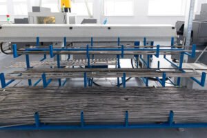
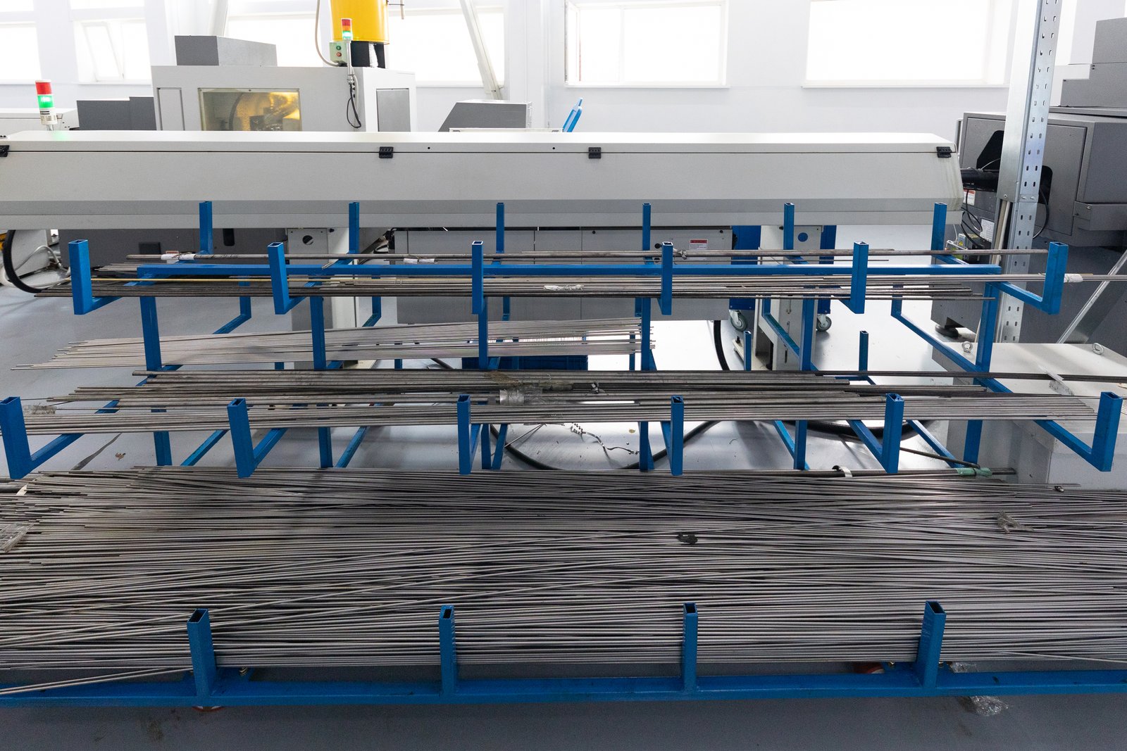
The Foundation: Uncoiling, Shearing, and Strip Accumulation
The journey of a perfect pipe begins long before the first roller stand. The initial material handling section—comprising the uncoiler, shear and end welder, and accumulator3—is the foundation of the entire process. Any instability or inconsistency introduced here will be amplified exponentially down the line. A failure in this section doesn't just create a bad pipe; it brings the entire multi-million dollar production line to a complete halt. Therefore, inspections here are non-negotiable.
For the uncoiler, the primary inspection points are the brake system and the expansion arbors. A faulty brake can lead to inconsistent tension, causing the strip to wander or buckle before it even enters the mill. This results in edge damage and makes consistent forming impossible. The bearings must also be checked for roughness or excessive play, as this can cause vibration. The shear and end welder, which create the continuous strip needed for non-stop production, must have sharp, properly gapped blades and correctly functioning clamps. A poor weld at this stage is a major safety hazard and is guaranteed to cause a jam or damage rollers when it reaches the forming section.
The accumulator (or looper) is the buffer that allows for this continuous operation. Whether it's a horizontal spiral or a vertical cage, its role is critical. Inspections must focus on the support rollers, bearings, and the pinch roll drive system. A seized roller in the accumulator can scratch the strip surface, a defect that will be carried through to the final product. More critically, a failure in the drive system can either starve the mill of material or fail to take up the strip from the welder, causing a catastrophic "bird's nest" of steel that can take hours, if not days, to clear safely. These components may seem secondary to the forming process, but their reliability is what enables high-efficiency, continuous production.
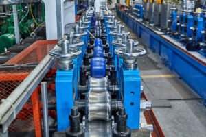
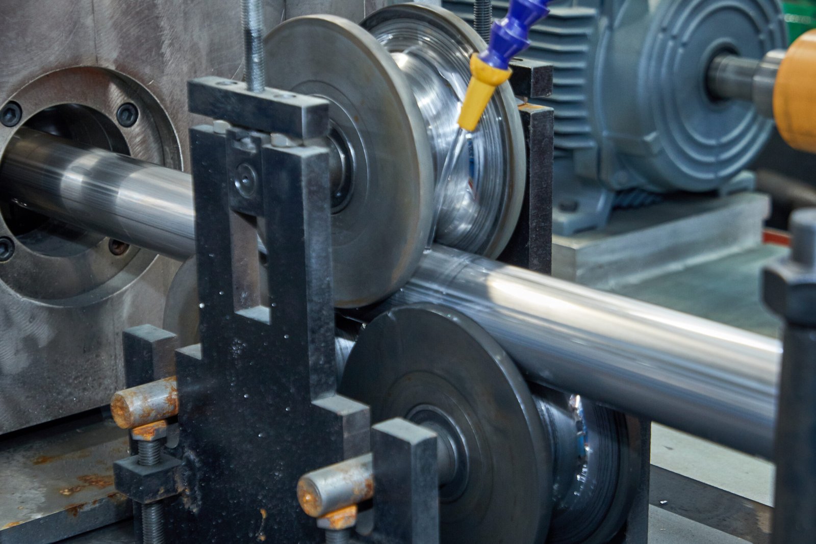
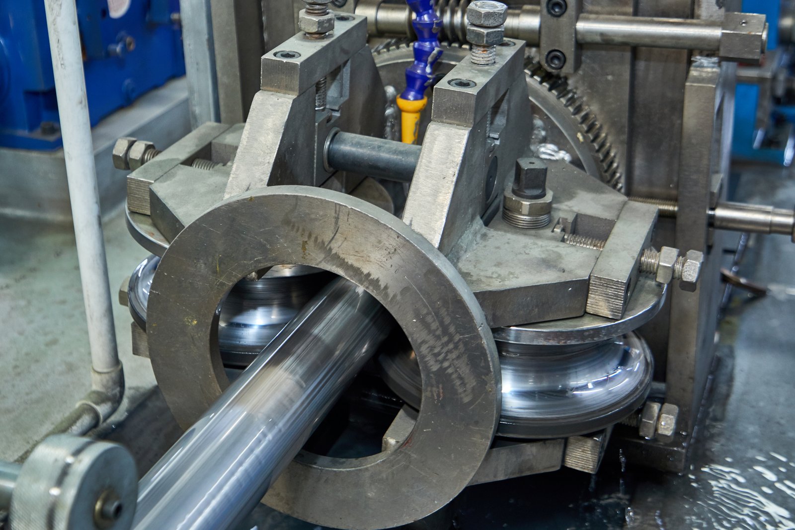
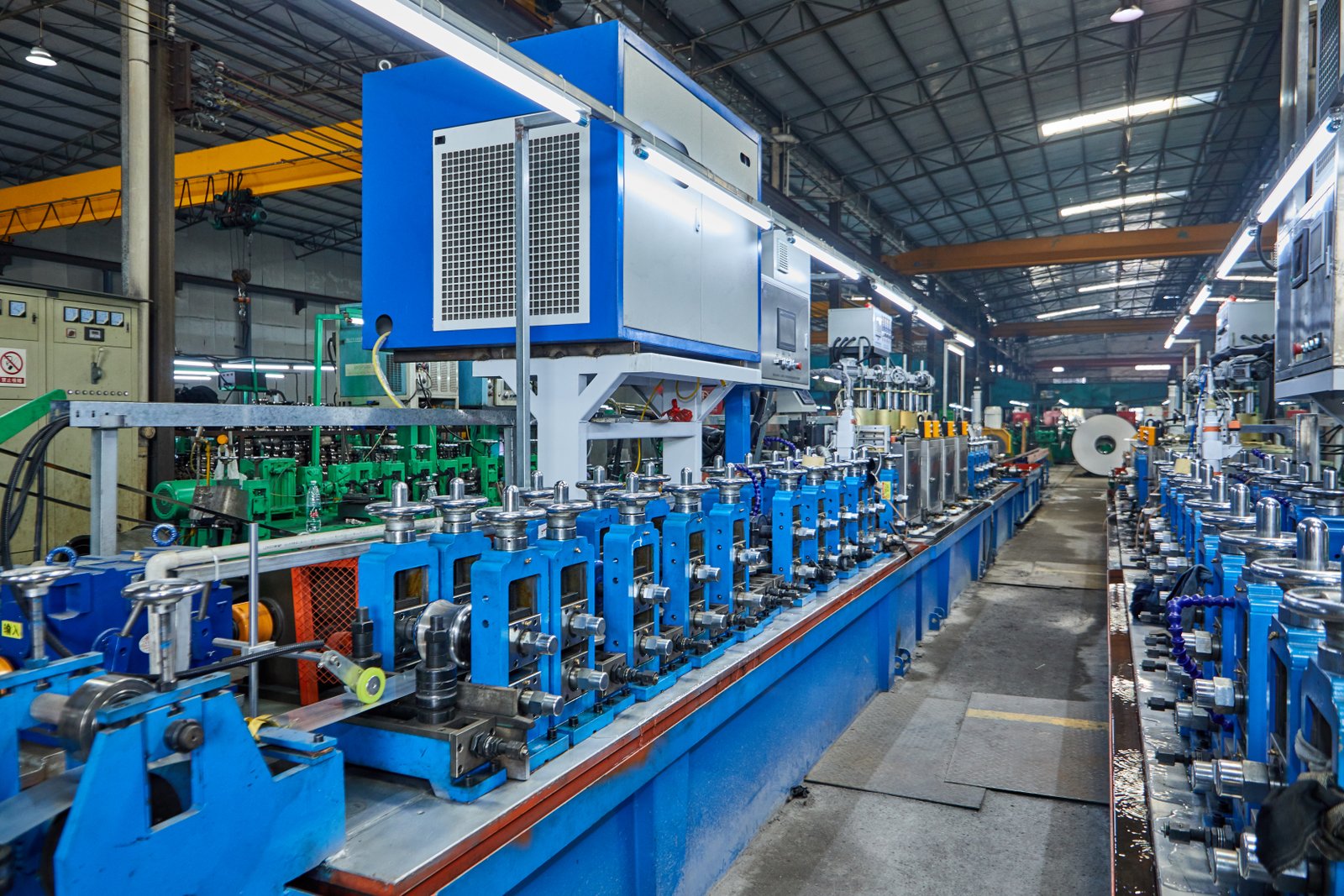
The Heart of Production: Forming, Welding, and Cooling
This is where the magic happens—where a flat strip is progressively shaped into a precision tube. This section contains the most critical and highest-wear components on the entire line. The forming and sizing stands, which house the rollers, demand the most rigorous inspection. Each roller shaft and bearing must be checked for signs of wear, misalignment, or damage. Misalignment here is the primary cause of common tube defects like twisting, concavity, and incorrect dimensions. Our XZS machines are built on robust, CNC-machined frames to ensure long-term stability, but the rollers themselves are consumable items that require constant vigilance. Their surface condition must be pristine, free from chips or grooves that would mar the tube's surface.
The welding unit is the single most important component for determining the tube's integrity. For a high-frequency (HF) welding line4, this means inspecting the inductor coil, the impeder, and the squeeze rolls. The inductor coil must be clean and properly aligned to ensure efficient energy transfer. The impeder, which concentrates the magnetic flux inside the tube, is a consumable item whose condition is directly proportional to weld quality. A degraded impeder leads to a weak, inefficient weld. The squeeze rolls, which force the heated edges together, must be perfectly aligned and apply the correct pressure. Too little pressure results in an incomplete weld, while too much pressure creates an excessive bead and can lead to stress fractures. In my experience, over 90% of weld quality issues can be traced back to a lack of preventive maintenance in these three components.
Immediately following the weld, the cooling section plays a crucial role in the tube's metallurgical properties. It's often neglected but is vital for quality. Inspections must ensure all spray nozzles are clear and functioning, delivering an even, consistent flow of coolant to the weld seam. Blocked nozzles can lead to uneven cooling, creating internal stresses and potential brittleness in the tube. The coolant itself must be managed—checking its concentration, filtration, and temperature. Sludge and metal fines in the coolant can be redeposited onto the tube surface, causing cosmetic defects, or can clog the system, leading to overheating at the weld box. A simple weekly check of nozzles and filters can prevent a host of quality problems that are otherwise difficult to diagnose.
| Section | Key Components for Inspection | Potential Failure Impact |
|---|---|---|
| Material Entry | Uncoiler Brake, Shear Blades, Accumulator Rollers | Inconsistent tension, strip damage, catastrophic line stoppage |
| Forming/Sizing | Forming Rollers, Sizing Rollers, Bearings, Shafts | Incorrect tube dimensions (ovality, diameter), surface defects |
| Welding | HF Inductor, Impeder, Squeeze Rolls, Power Supply | Poor weld integrity, seam cracks, excessive scrap |
| Cooling & Cutoff | Coolant Nozzles, Coolant Tank, Cutoff Saw/Blade | Metallurgical defects, poor surface finish, inaccurate lengths |
The Finish Line: Sizing, Straightening, and Cutting
After the tube is formed and welded, it enters the final stages that determine its dimensional accuracy and final form. The sizing section, which works similarly to the forming section, gives the tube its final precise diameter and roundness. These rollers and their bearings require the same level of detailed inspection as their forming counterparts. Even a small amount of wear here can push the final product out of its specified tolerance. For a client producing hydraulic tubing, where precision is paramount, maintaining a tolerance of ≤ ±0.05 mm is only possible with perfectly maintained sizing stands.
The straightening section, or turkshead, is next. It's used to correct any minor twist or bow in the tube. The rolls in the turkshead apply pressure from multiple axes and must be inspected for surface condition and alignment. Improperly set straightening rolls can do more harm than good, inducing stress into the tube or marking its surface. This is another area where operator skill and meticulous maintenance converge to create a high-quality product.
Finally, the cutting unit, whether it's a friction saw, cold saw, or laser cutter, determines the final length of the product and creates a clean, burr-free end. For saws, blade sharpness and integrity are critical. A dull blade requires more pressure, which can deform the tube end and create excessive heat. The clamping mechanism that holds the tube during the cut must also be inspected to ensure it grips securely without damaging the tube. The measuring system, whether a physical limit switch or an encoder, must be verified regularly to ensure length accuracy. A drift in this system can lead to an entire batch of product being cut to the wrong size—a costly and entirely preventable error.
How can operators effectively clean and lubricate machinery to prevent downtime?
Do you find that no matter how much you lubricate, you're still facing premature wear and breakdowns? The problem often isn't the amount of lubrication, but the method. Simply applying new grease over old, contaminated grease is a recipe for failure. Effective maintenance starts with a commitment to cleanliness.
To prevent downtime, operators must first clean all fittings and surfaces before applying lubricant. Use the correct type and amount of lubricant as specified by the manufacturer, establish a consistent routine, and ensure lubricants are stored properly to prevent contamination before use cleaning and lubrication best practices.
This clean-first principle is a game-changer. I once visited a furniture factory in India struggling with frequent bearing failures on their heavy-duty tube mill, despite a diligent weekly lubrication schedule. When I observed their process, I saw the issue immediately: the technician was applying fresh grease directly onto fittings caked with a mixture of old grease, metal dust, and grime. They were essentially injecting an abrasive paste into their bearings. We revised their procedure to a simple two-step process: "Wipe clean, then lubricate." This single change in habit cut their bearing-related downtime by over 80% within three months common lubrication mistakes case studies5. It highlights that the most effective PM tasks are often the simplest, requiring discipline rather than complex tools. The goal isn't just to add lubricant; it's to ensure a clean, effective film of the right lubricant is protecting the component.

The Science of "Clean": Beyond a Superficial Wipe-Down
The principle "lubricate clean" sounds simple, but its effective implementation requires a deeper understanding of contamination control. Contamination is the number one cause of lubricant-related failures. A study by the National Research Council of Canada found that up to 82% of wear-related failures are caused by particle contamination in the lubricant impact of lubricant contamination on machinery6. These particles can be external (dirt, dust from the environment) or internal (tiny metal fragments generated from normal wear). When you apply new grease to a dirty fitting, you are using the pressure of the grease gun to force these abrasive particles directly into the bearing's critical rolling elements.
Effective cleaning is therefore not just a preparatory step; it is an integral part of the lubrication process itself. Operators and technicians should be trained to use lint-free cloths to wipe down the grease fitting (zerk) and the area immediately surrounding it. For gearboxes and hydraulic systems, this extends to cleaning fill ports and breathers before opening them. This prevents airborne contaminants from entering the reservoir. For our XZS high-frequency welding lines, cleanliness around the weld box and cooling system is paramount. Metal dust and coolant residue can create conductive paths, leading to electrical shorts, or can clog cooling channels, leading to overheating.
Furthermore, the tools used for lubrication must also be kept impeccably clean. Grease guns should have their tips covered when not in use. Transfer containers for oils should be dedicated to a single lubricant type, be sealed, and be cleaned regularly. I’ve seen workshops where a single, open-top pail is used to top off every machine on the floor—a catastrophic cross-contamination scenario. Establishing a culture of cleanliness, where a clean workspace and clean tools are seen as essential for machine reliability, provides a greater ROI than almost any other maintenance activity.
Lubricant Selection and Application: Precision, Not Excess
More is not better when it comes to lubrication. Over-lubrication can be just as damaging as under-lubrication. For bearings, excessive grease can cause the rolling elements to churn the grease, leading to increased friction, heat, and energy consumption. This process, known as viscous drag, can cause temperatures to rise to a point where the oil separates from the grease's thickener, destroying its lubricating properties dangers of bearing over-lubrication7. For electric motor bearings, excess grease can be forced into the motor windings, causing insulation failure and a costly burnout. Our fully automated PLC-controlled lines often have alarms for motor over-current, which can sometimes be traced back to something as simple as over-zealous lubrication.
Selecting the correct lubricant is a science in itself. Using a general-purpose grease across an entire tube mill is a common but costly mistake. Different components have vastly different requirements. The high-speed bearings in a cutting motor need a different viscosity and additive package than the slow-moving, high-pressure gears in a main drive gearbox. The manufacturer's recommendation is the bible in this regard. At XZS, we specify the precise lubricant type (e.g., ISO VG 220 gear oil, NLGI #2 EP grease) for each component because we have matched it to the operational loads, speeds, and temperatures of our designs. Using the wrong type can lead to film failure, accelerated wear, and ultimately, breakdown.
A best practice for ensuring the right lubricant is used every time is to implement a color-coding or tagging system. Each lubricant type in storage is assigned a color. A matching color tag is placed on every application point on the machinery. The transfer containers and grease guns for that lubricant are also marked with the same color. This simple, visual system removes guesswork and makes it nearly impossible for an operator to accidentally apply hydraulic oil to a gearbox. It’s a low-cost, high-impact reliability tool that standardizes the process and reduces human error.
| Lubrication Task | Ineffective Method | Effective Method |
|---|---|---|
| Greasing a Bearing | Applying new grease to a dirty fitting until it purges. | Wiping the fitting clean, applying a calculated, specific amount of the correct grease. |
| Topping off Oil | Using an open, dirty container to pour oil into an unclean fill port. | Using a sealed, dedicated, clean container to pour into a wiped-clean fill port. |
| Lubricant Storage | Drums stored outdoors, open to elements; unlabeled containers. | Drums stored indoors at a stable temp; color-coded, sealed transfer containers. |
| Tool Cleaning | Grease gun tip left exposed to collect dust and grime. | Grease gun tip is wiped before use and covered after use. |
Storage and Handling: Protecting Lubricants Before Use
A lubricant's journey to failure can begin long before it ever reaches the machine. Improper storage and handling practices can introduce contamination or degrade the lubricant, rendering it ineffective from the start. Lubricants should be stored in a dedicated, clean, dry, and climate-controlled area. Temperature fluctuations are a major enemy. As a drum of oil heats and cools, it "breathes," drawing in moist, dirty air from the atmosphere, which leads to water contamination and oxidation of the oil. Storing drums indoors at a stable temperature is critical.
Drums should also be stored horizontally on racks. If they must be stored upright, they should be tilted slightly or placed under a cover to prevent water and debris from pooling on the top surface around the bungs. This water can be drawn into the drum during the thermal breathing cycle. First-In, First-Out (FIFO) inventory management is also essential. Using the oldest stock first ensures that lubricants are not kept beyond their recommended shelf life, as their additive packages can degrade over time.
Finally, the way lubricants are dispensed is a critical control point. Bulk tanks should be fitted with desiccant breathers to remove moisture from incoming air and proper filtration on the outlets. When transferring to smaller containers for use on the factory floor, use sealed, properly labeled containers. As a rule, galvanized steel containers should never be used for storing lubricants containing certain additives, as they can react with the zinc coating to form soaps that can clog filters and orifices in machinery. By treating lubricants as the critical, precision machine components they are—from the moment they arrive at your facility to the moment they are applied—you create a closed loop of reliability that prevents contamination at every step.
What steps should be taken to calibrate machinery for optimal performance?
You're producing tubes, but are you producing them to the exact specification every single time? Inconsistent quality, high scrap rates, and customer complaints often stem from a lack of proper calibration. Achieving optimal performance requires a dedication to precision that goes beyond basic maintenance and enters the realm of metrology8.
To calibrate machinery for optimal performance, you must systematically verify and adjust key settings, including roller alignment and gap, welding power and frequency, and cutting system length measurement, using precision tools like micrometers, laser alignment devices, and calibrated gauges.
Calibration is the difference between simply running a machine and mastering it. I recall a client in the United States, a manufacturer of high-spec heat exchangers, who was struggling with a persistent 5% scrap rate due to tubes not meeting the tight ≤ ±0.05 mm tolerance. They believed it was a material issue. However, by performing a full calibration of their sizing stands with a set of feeler gauges and a micrometer, we found that the roller gaps on one side were off by a mere 0.1 mm. This tiny deviation was enough to cause the issue. After recalibrating the stand, their scrap rate dropped to less than 0.5%. This demonstrates that calibration isn't an occasional task but a continuous process of verification and adjustment that directly translates to profitability in precision manufacturing9.
Calibrating the Forming and Sizing Passes
The dimensional accuracy of a welded tube is determined entirely by the precise setup and calibration of the roller stands. This is a meticulous process that cannot be rushed or eyeballed. It requires the use of precision measuring tools like calipers, micrometers, and feeler gauges10. The goal is to ensure that the gap between the top and bottom rollers, and the alignment of the side rollers, perfectly matches the progressive forming design for the specific tube size being produced. This process begins with establishing a true baseline, ensuring the mill bed itself is level and the stand shafts are perfectly parallel.
The first step in roller calibration is to perform a "bottom-line" alignment. This involves running a string line or laser along the centerline of the bottom shafts of all the stands to ensure they are in a perfectly straight line and at the correct height. Any deviation here will make it impossible to achieve a consistent form. Once the bottom line is set, the vertical and side rollers are calibrated for each pass. This involves using feeler gauges to set the precise gap that will gently bend the steel strip into its next shape. Too large a gap will not form the material correctly, while too small a gap will thin the material and introduce stresses.
This calibration is not a one-time event. Tooling changes for different tube diameters require a full recalibration. Furthermore, normal operational stresses and vibrations can cause settings to drift over time. This is why periodic verification is essential. A quick check with a feeler gauge at the start of a new run or a new shift can catch a drifting setting before it produces thousands of feet of out-of-spec tubing. On our XZS tube mills, we design quick-change tooling systems to minimize downtime during size changes, but we always emphasize to our clients that the time saved must be reinvested into a proper calibration procedure to ensure the next run is perfect from the first foot to the last.
Fine-Tuning the Welding and Scarfing Parameters
A dimensionally accurate tube with a weak weld is a failed product. Calibrating the welding process is crucial for ensuring the structural integrity of every tube you produce. For high-frequency (HF) welding11, this involves a multi-faceted calibration of power, frequency, and the physical setup of the squeeze rolls. The power setting determines the amount of heat introduced to the strip edges. Too little power results in a "cold" weld with incomplete fusion, while too much power can burn away material and create a brittle seam. The optimal power level is a function of material type, thickness, and line speed, and it must be carefully calibrated and documented for each product.
The physical calibration of the squeeze rolls is equally critical. These rolls must be aligned to apply pressure perfectly at the apex where the heated edges meet. The amount of pressure is a delicate balance. It must be sufficient to forge the edges together and expel any oxides from the weld zone, but not so great as to create an excessive internal or external bead or distort the tube's shape. We use a combination of visual inspection of the "v-shape" of the strip entering the weld zone and precise measurement of the resulting weld bead to calibrate this pressure.
The scarfing tools, which remove the excess weld bead from the outside (OD) and sometimes the inside (ID) of the tube, also require precise calibration. The cutting tool must be set at the correct height and angle to remove the bead smoothly without gouging the parent material of the tube. An improperly calibrated OD scarfer will leave a raised bead, which is unacceptable for many applications, or a deep tool mark, which creates a stress riser and a potential failure point. Modern systems often use multi-axis controls to maintain the position of the scarfing tool relative to the tube surface, but these systems still require initial setup and periodic verification to ensure they are performing optimally.
| System | Calibration Parameter | Tool Used | Impact of Miscalibration |
|---|---|---|---|
| Forming Stands | Roller Gap & Alignment | Feeler Gauges, Micrometer, Laser | Incorrect tube diameter, ovality, twisting |
| HF Welder | Power Level & Frequency | System PLC, Ammeter | Weak weld, burn-through, seam defects |
| Squeeze Rolls | Pressure & Alignment | Visual Check, Pressure Gauges | Incomplete fusion, excessive weld bead, tube distortion |
| Cutoff System | Length Measurement | Calibrated Tape Measure, Encoder | Incorrect tube lengths, high scrap rate |
Ensuring Accuracy in the Cut
Producing a perfectly formed and welded tube is pointless if it is cut to the wrong length. The final calibration step involves the cutting system. Whether it’s a high-speed friction saw or a precision cold saw, the system that measures the tube and triggers the cut must be meticulously calibrated. For most modern mills, this measurement is done via an encoder wheel that rides on the surface of the tube, tracking the length of material that passes by.
The encoder itself must be calibrated. This is typically done by making a test cut, then manually measuring the cut length with a calibrated tape measure or length standard. Any discrepancy between the machine's target length and the actual measured length is then programmed into the PLC as an offset. This process must be repeated regularly, as wear on the encoder wheel or slight slippage can cause the measurement to drift over time. A client producing structural tubing for the construction industry found that performing this simple check once per day saved them from entire bundles of product being rejected for being too short.
Beyond length, the physical components of the cutter must also be calibrated. The clamping system must be adjusted to hold the tube securely without crushing it. The saw blade or cutting tool must be advanced at the correct speed and pressure to ensure a clean, square cut with minimal burr. For flying cutters that move with the tube to make a cut without stopping the line, the synchronization between the line speed and the cutter's travel speed must be perfect. Any error here results in an angled cut. This final calibration step ensures that the quality and precision achieved throughout the entire forming and welding process are delivered in the final product that reaches the customer.
How can a maintenance schedule be developed to ensure zero downtime in tube manufacturing?
You're performing maintenance, but do you have a true strategy? A random collection of tasks is not a schedule. To achieve zero downtime, you need a documented, living plan that organizes tasks, assigns responsibility, and uses data to drive continuous improvement, turning maintenance from a chore into a competitive weapon.
To develop a zero-downtime maintenance schedule, first inventory and prioritize all machinery. Then, define specific daily, weekly, and monthly tasks for each asset, assign clear responsibilities, and use a CMMS or logbook to track completion and analyze data for optimization.
This is about building a system, not just a list. A few years ago, I helped an industrial equipment distributor, one of our EPC contractor clients, create a PM schedule12 for their end-user’s new large-diameter tube mill. They had all the components but no structure. We started with a simple spreadsheet, listing every major component from the uncoiler to the run-out table. We assigned a priority level to each and then collaboratively defined clear, actionable tasks—like "Verify coolant flow to weld box" (Daily) or "Change gearbox oil" (Annually). We assigned each task to a specific role (Operator or Technician). Within six months, they had a comprehensive log of their maintenance activities, which allowed us to identify problem areas and adjust task frequencies. They had created a dynamic, intelligent system that put them in complete control of their asset's health.
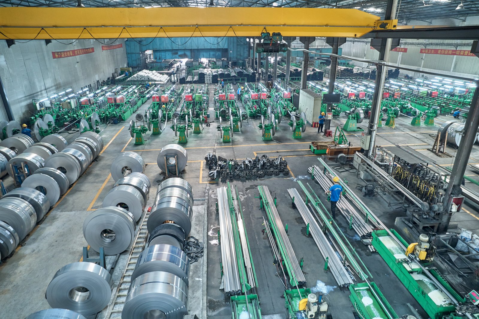
Step 1: Asset Inventory and Criticality Analysis
You cannot maintain what you have not documented. The foundational step in creating any maintenance schedule is to conduct a thorough inventory of every piece of equipment that contributes to the production line. This goes beyond just listing "Tube Mill." It means breaking the line down into its core systems and subsystems: Uncoiler, Shear/End Welder, Accumulator, Forming Section (Stand 1, Stand 2, etc.), Weld Box, Cooling Trough, Sizing Section, Straightener, Cutoff Saw, and Run-out Table. Each of these should be logged, including key information like manufacturer (e.g., XZS), model number, serial number, and installation date.
Once you have a complete inventory, the next crucial step is to perform a criticality analysis13. Not all assets are created equal. A failure of the main drive gearbox is a line-stopping catastrophe, while a failure of a single roller on a non-driven run-out table might be a minor inconvenience. You must rank each asset based on its impact on production, safety, and quality. A simple 1-5 scale can work, where 1 is a non-critical component with built-in redundancy, and 5 is a single-point-of-failure asset that would cause an immediate and total shutdown.
This analysis is the strategic heart of your PM schedule. It allows you to focus your limited resources—time, budget, and personnel—where they will have the greatest impact. A study by the ARC Advisory Group suggests that a well-prioritized PM plan can yield the same reliability results with 20-30% less work than an un-prioritized one. For example, the high-frequency welder and the main drive system would be ranked as highly critical (Level 5), demanding the most frequent and detailed inspections. The lubrication pump for the run-out table bearings might be a Level 2, requiring less frequent checks. This data-driven approach ensures you are not over-maintaining non-critical items at the expense of the components that truly keep you in business.
Step 2: Defining Tasks, Frequencies, and Responsibilities
With your assets inventoried and prioritized, you can now define the "what, when, and who" of your maintenance plan. For each asset, you need to list specific, actionable maintenance tasks. Vague instructions like "Check gearbox" are useless. A good task description is unambiguous: "Check gearbox oil level via sight glass; oil must be between high and low marks." Or, "Use infrared thermometer to check gearbox operating temperature; record reading and report any temp over 80°C." These tasks should be sourced from OEM manuals (like those we provide at XZS), industry best practices14, and your own maintenance history.
Next, assign a frequency to each task. This creates the actual "schedule." Frequencies are typically time-based (Daily, Weekly, Monthly, Quarterly, Annually) or usage-based (Every 100 hours of operation, Every 5000 tubes produced). A robust schedule uses a mix of both. For example, a visual inspection might be daily, lubrication weekly, a detailed mechanical inspection monthly, and an oil change annually or after 2,500 hours of operation, whichever comes first. Our PLC-controlled lines make usage-based scheduling easy by automatically tracking run-time and cycle counts.
ly, and crucially, assign a clear responsibility for every single task. This creates accountability. "Operator" or "Maintenance Technician" are common roles. Daily tasks that are quick and visual are often best assigned to the machine operator, as they are the most familiar with the machine's daily behavior. More complex tasks requiring specialized tools or training should be assigned to the maintenance department. This clear division of labor ensures that nothing falls through the cracks and fosters a sense of ownership over the equipment's health at all levels of the organization.
| Frequency | Sample Tasks for a Main Forming Stand | Responsible Role |
|---|---|---|
| Daily | Visual inspection of rollers for debris or damage. Check for unusual noises or vibrations. Verify coolant flow to rollers. | Operator |
| Weekly | Lubricate all grease points on bearing housings. Check tension of drive chains/belts. Wipe down stand and shafts. | Operator/Technician |
| Monthly | Verify roller alignment with feeler gauges. Inspect bearings for excessive play or roughness. Check torque on all mounting bolts. | Technician |
| Annually | Remove shafts and bearings for detailed bench inspection. Change oil in drive gearbox. | Technician |
Step 3: Documentation, Execution, and Continuous Improvement
The most well-designed schedule is worthless if it lives only on paper or in a manager's head. The schedule must be executed, and its completion must be documented. This is where a Computerized Maintenance Management System (CMMS) becomes invaluable. A CMMS digitizes the entire process, automatically generating work orders, sending reminders, and providing a central database for all maintenance activities. For companies without a CMMS, a structured system of checklists and logbooks can also be effective, though more labor-intensive.
The act of documenting completion is non-negotiable. It provides a historical record of the asset's health, which is invaluable for troubleshooting and diagnostics. If a bearing fails, a quick look at the maintenance log can reveal if it was being lubricated correctly, if overheating had been previously noted, or if it was simply at the end of its expected life. This data transforms you from a reactive fixer into a proactive analyst.
This historical data is the fuel for the final, most important step: continuous improvement. Your maintenance schedule should be a living document, not a static one. On a quarterly or semi-annual basis, you must review the data you have collected. Are you having frequent failures on a component that only has a monthly check? Perhaps that check needs to be weekly. Is a component that gets a weekly check consistently found to be in perfect condition? Perhaps you can move that to a bi-weekly schedule and reallocate that labor time to a more critical area. This feedback loop—Plan, Do, Check, Act—is what allows you to relentlessly optimize your schedule, fine-tuning your way towards the ultimate goal: zero unplanned downtime.
Conclusion
Ultimately, achieving zero downtime is not about having the most expensive tools, but the most disciplined strategy. A proactive playbook built on scheduled, data-driven maintenance transforms your machinery from a potential liability into a reliable, high-performance asset, ensuring consistent quality and maximizing profitability.
-
Dive deeper into how CBM works and why it's more efficient than time-based approaches ↩
-
Download or view a detailed inspection checklist to improve your own maintenance process ↩
-
Understand why material entry section reliability is critical for continuous tube production ↩
-
Discover the importance of HF welding and its required maintenance for strong tube weld seams ↩
-
See practical examples of how clean lubrication reduces downtime and failure rates in factories. ↩
-
Discover statistics and explanations behind contamination-related failures and their prevention. ↩
-
Prevent costly equipment damage by understanding the dangers of excessive lubrication in machinery. ↩
-
Learn why metrology is critical for precision and calibration in tube mills ↩
-
Discover the direct financial impact of calibration on manufacturing efficiency and waste reduction ↩
-
See examples and best practices for selecting precision tools for machinery calibration ↩
-
Understand the technical principles and calibration needs of high-frequency welding in tube production ↩
-
Discover best practices for building and implementing preventive maintenance schedules in factories ↩
-
Understand why criticality analysis helps prioritize resources for maximum equipment reliability ↩
-
Find guidelines for setting frequencies and responsibilities in manufacturing maintenance programs ↩